Kirjoittaja
Aihe: Swiss Caravaner searching for Help - Primus Aquaflex AQWE6 (Luettu 10160 kertaa)
Kirjoittaja
Aihe: Swiss Caravaner searching for Help - Primus Aquaflex AQWE6 (Luettu 10160 kertaa)
« Vastaus #1 : 27.03.2026 kello on 11:22 »
« Vastaus #2 : 27.03.2026 kello on 11:41 »
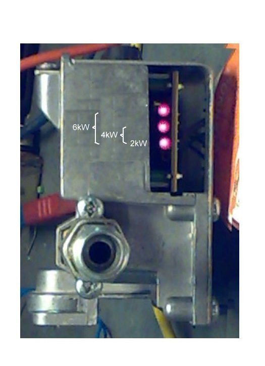
Hello, that was quick  The 2 LED are active when i activate the Gas button. The 3rd LED is only active for 1sec, and then turns off. i resoldered the cable socket on the board (i think its the flame detector with the black cable going down to the heater) it has only 1 pin. you think the cable is broken?
« Vastaus #3 : 27.03.2026 kello on 13:53 »
Hi, seems some misinterpretation to me.... @LaemmitinGuru: "Epaeilen, ettae sinulla on kaasuventtiilin valkoinen liitin murtunut juotoksista" < I suspect you got broken solderjoint at gasvalves white connector > "Meneekoe tosiaan musta johto liekin tunnistin liittimeen? Sehaen tarkoittaa, että kaerjet on vaihdettu" < Black wire to the flame detector? It means electrodes has been swapped > Just a comment.... Black wire to the flame detector? Should'n be indeed. That wire is a of special insulation like PTF ("teflon"), bright non-coloured, slightly stiff, the only of its kind in the apparatus. Do you have a multimeter at hand? I'll come back to this at next night (if not solved before that)
« Vastaus #4 : 28.03.2026 kello on 05:09 »
At least here in Finnland we consider these repairs of caravanheaters as "business as usual". Some of us are self sufficient, some may embark themselves by help of fellow caravanpeople. But to comform the way of helping it is always necessary to know about resourses and abilities available of those been helped. So you might shortly tell something about capabilities of yours in technical matters. Can you read schematics? Can you conduct electrical measurements assisted/unassisted? Have you basic understanding in electronics. Aquaflex is not too complicated thing in general and we can guide you throught fault tracing if you feel confident in making some electrical measurements. BTW, you didn't specify if your starting attemps ends up into alarm state?
« Vastaus #5 : 28.03.2026 kello on 11:38 »
good morning, i checked the flame cable, its the white stiffer cable (going into the burner) but optically, i would say, its not cracked, and i dont know if i can unplug it down on the burner side? question: is it possible that the temperature sensors are broken? what would be the resistance in OHM of these? My understanding is as well, that the 3 LED on the Gas Magnet Valve should be active, according to the power i pull?, so 2,4,6kw? Thanks
« Vastaus #6 : 28.03.2026 kello on 18:11 »
@Scoop im working since 25 years as a systems engineer in the IT Datacenter Environment. My education then, end of 2002 included some electric explaing, so i can measure voltage, conduction etc, also very small understanding of reading schematics, i have basic soldering skills, but thats it. about your question if it turns to a failure. On the controlpanel there is only a green led, when i press the big button to enable the heater pump. nothing red appears, even after after 15min waiting. i thought in the past, i had once a red led on, when i forgot to open up the gas bottle valve. In this years trouble shooting i never got a red led.
« Vastaus #7 : 31.03.2026 kello on 09:30 »
@Scoop
im working since 25 years as a systems engineer in the IT Datacenter Environment. My education then, end of 2002 included some electric explaing, so i can measure voltage, conduction etc, also very small understanding of reading schematics, i have basic soldering skills, but thats it.
about your question if it turns to a failure. On the controlpanel there is only a green led, when i press the big button to enable the heater pump. nothing red appears, even after after 15min waiting. i thought in the past, i had once a red led on, when i forgot to open up the gas bottle valve. In this years trouble shooting i never got a red led.
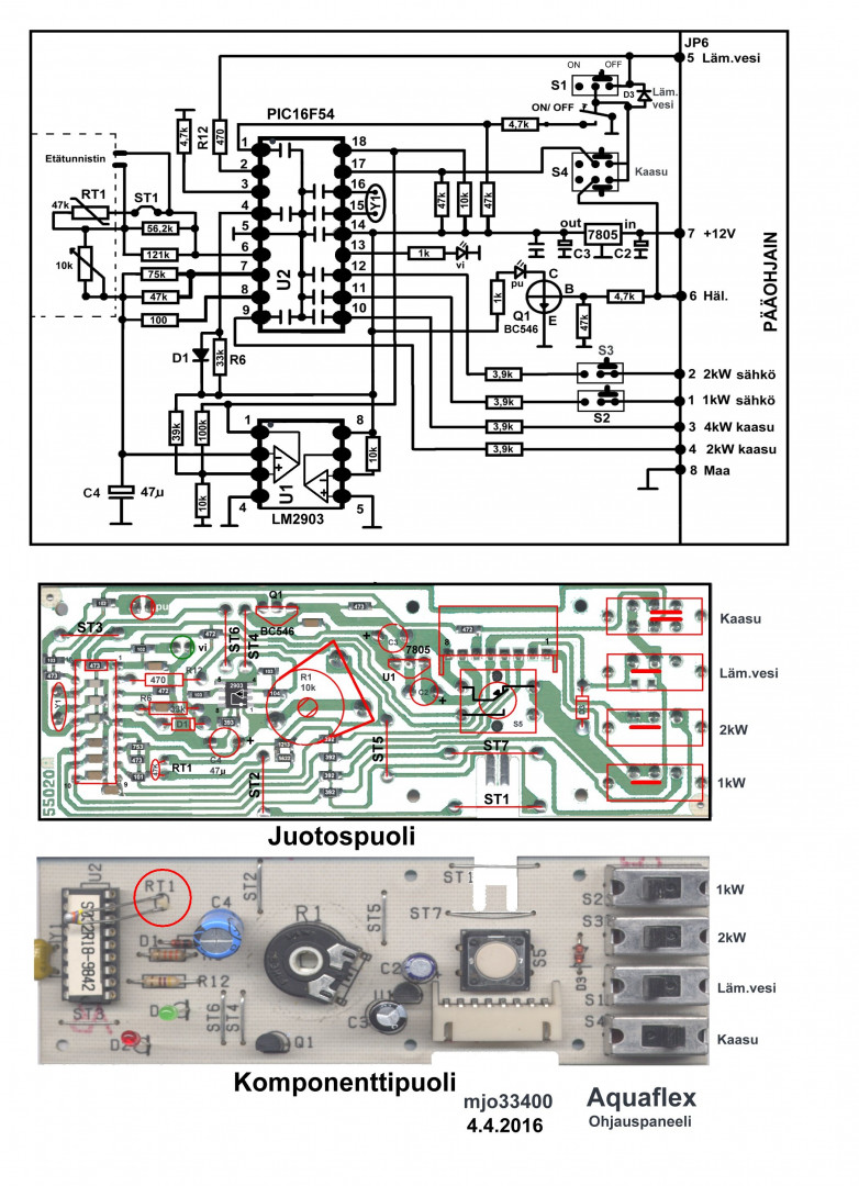
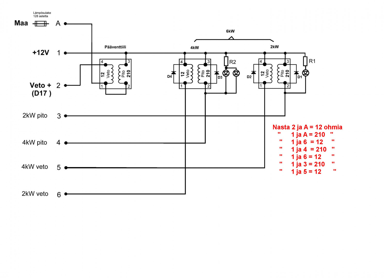
Oletko todennut, että lämmitin käynnistyy, mutta kolmosteho ei pysy päällä? Kolmostehon pitää pysyä päällä noin 17 sekuntia jonka jälkeen kakkosteho on päällä tasan minuutin. Tämä sykli toistuu niin kauan kuin kolmostehoa tarvitaan. Jos lämmitin ei käynnisty niin sen pitää mennä häiriötilaan. Tarkista ohjauspaneelin NTC-vastuksen juotokset. Vastusarvo on tuo kytkentäkuvan 47 kohmia.
« Vastaus #8 : 31.03.2026 kello on 10:15 »
@mjo33400, thank you for this advice, i will check this when i get back home. Just to be sure, you are speaking about the 3 LED on the Gas Switch module? Kind regards, Patrick
« Vastaus #9 : 31.03.2026 kello on 19:44 »
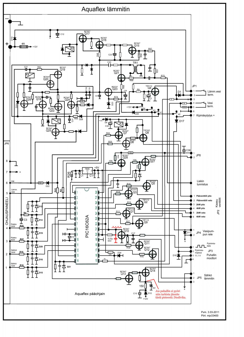
Patrick, as LammitinGuru stated, the temperature sensor (NTC) is roughtly 47Kohm but it is parallel with 56,2kohm and 121kohm giving 21,13kohm total. It is equated as 1/((1/47kohm) + (1/56,2kohm) + (1/121kohm)) (I expect you don't have remote sensor equipped) The reason to focus in temperature sensing is obviously in that the heater doesn't start but doesn't enter alarm state either. So the controller MCU sees everything OK without need to call for heat. The conclution ==> temperature is measured wrong. /* @Mjo: Tuossa kytkennässä häiritsee se että jännite mittausketjulle on otettu kontrollerin navasta 6 joka ei välttämättä/stabiilisti saavuta syöttävän regulaattorin jännitettä. Noin nopeasti silmäiltynä en löytänyt LAY-OUT-kuvaan verrattuna virhettä mutta itse en suunnittelisi piiriä noin. Oletko sattumoisin tullut koskaan mitanneeksi minkä verran kuutosnavassa saattaisi olla jännitteen alenemaa Vdd:en verrattuna. Kysyn siksi että sen tiedon perusteella voisi arvioida muutosta jos sellaista on päässyt tapahtumaan. MCU:n navat 7 ja 8 ilmeisesti pystyisivät paljastamaan totaalin katkoksen joissain kohtaa mittausketjua. MCU ilman AD-muuntimia ei tietystikään voi olla kovin hienovarainen tuossa suhteessa mutta ilmeisesti itsediagnoosiin on ainakin varauduttu. Mielenkiintoista. */ Patrick, in case NTC is not failed, can you measure voltages on MCU pins 6,7,8 and 18?
« Vastaus #10 : 31.03.2026 kello on 22:42 »
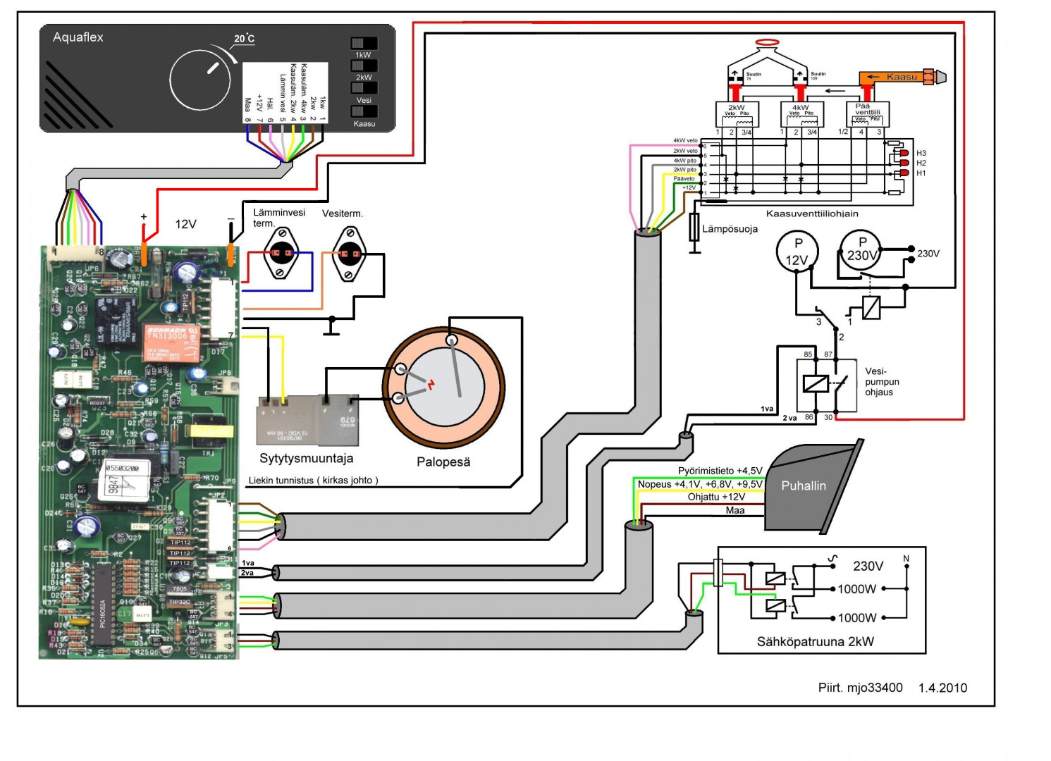
I need to rectify my last comment. In the entry you clearly stated that the controller starts the heating sequence, it means heating actually is called for. I should have read the entry again after being absent awhile. Some rethinking is needed now. So you told that heating sequence proceeds somewhat, looks like to the point where ignition in expected. Those LEDs in the valve PCB indicates that holding coils are energized but they does not necessarily open without activation coils energized. Now the question arises if you did hear the clunking sound they make on opening? The red alarm LED in the control panel should light up on missed ignition anyway... On the last picture in #5 the valve unit connector looks like slided partly away of its position? Do I see it correctly?
« Vastaus #11 : 1.04.2026 kello on 20:23 »
@Mjerica i checked the 48k Ohm resistor, its 29k Ohm, i hope i catched the correct one? Since this is parallel with 2 others, you mentioned it should be 21.3 k Ohm? i realized the red diode on the control panel was no more soldered correctly to the controller board, i fixed that. now i try to measure the voltage on the mainboard on the mentioned ports, MCU pins 6,7,8 and 18, what are the expected values? at least now the red error LED works again on the control panel, but i have still the same problem, please see the video under this link: https://share.icloud.com/photos/077ElUcjtaMszZ_tRd7OL2YVg
« Viimeksi muokattu: 1.04.2026 kello on 20:42 »
« Vastaus #12 : 2.04.2026 kello on 04:30 »
Patrick, in this picture you are measuring between wrong points. (75k&47k connected to U2 pin 7) In the picture, the temperature sensor RT1 is just behind your plusprobe tip. "i realized the red diode on the control panel was no more soldered correctly to the controller board" - Now this begins to make sense, we were dealing with two independent faults. That is often confusing. One fault left.... for now on, everything should become more straightforward. - Let's leave MCU pins 6,7,8,18 for a moment, we'll come back to these later if necessary. @Patrick: "I hear the blower turns on, after 15sec the gas switch opens (on the gas switch for a short time the 3rd led is active, then only the 2 top leds are active > see attached picture), the ignitor is active for 2-3 secs, then the blower starts to turn faster and nothing happens" In the video, what I saw, (or I believe I saw), it looks like no valve LED on until in the final moment of ignition. And then, only very short flash simultaneously with (main?)valve opening sound followed by shutdown to the alarm state. Do you see/hear something different? My (kind of) impression is that valve activation makes supply voltage to drop abruptly and causes shutdown and terminates the starting sequence. Some other explanations are possible though. I will check the video some more time tomorrow. It would be interesting know how voltages behave in (main controller PCB) PIC16C62A pins 26, 27 and connector JP2 pins 4, 3 respectively in starting sequense. But these needs very carefull handling of probes not to make damaging short circuits.
« Vastaus #13 : 2.04.2026 kello on 11:37 »
@Mjerica thank you for your answer, i just measured the correct resistor, and its 27.4 k Ohm. i will try to measure the PCB-Board Pins 26, 27, and JP2 pin 4,3 tonight. The video i posted, is the exact problem situation, its every time the same behavior.
« Vastaus #14 : 2.04.2026 kello on 11:43 »
@mjo33400, thank you for this advice, i will check this when i get back home. Just to be sure, you are speaking about the 3 LED on the Gas Switch module? Kind regards, Patrick
Kyllä puhun.
|